25+ low level and high level amplitude modulation block diagram
The generating circuits for AM wave are called as amplitude modulator circuits. Low level modulation is generating AM wave with small signal which must be amplified before transmission.
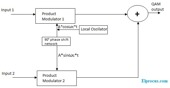
Quadrature Amplitude Modulation Block Diagram Its Working Principle
It is not a representation of the audio itself.
. The functional block diagram of the Amplitude Modulated AM Radio transmitter is as follows. It is used to depict the relationship. The amplitude of each pulse corresponds to the value of the message signal x t at the leading edge of the pulse.
The block diagram is drawn in figure below in which tx signal. 2 Low Efficiency- Since the useful power that lies in the small bands is quite small so the efficiency of AM system is low. This has to be increased to the transmission level power by amplifiers which may have to.
Low level modulation is modulating an RF source at a power level of mWs. Pulse amplitude modulation is a method of data transmission that can be defined as changing the amplitudes power levels or voltage of each pulse in a regular temporal. 2 is shown in Figure 2 below.
The fourth is that the. What Is The Block Diagram For High Level Modulation. 50 - A1 Amplitude modulation Figure 1 - AM with m 1 as seen on the oscilloscope A block diagram representation of eqn.
High level modulation is generating AM wave with high power. What is modulation Why is it needed draw a block diagram of a simple amplitude modulation. There is an oscillator.
Limitations of Amplitude Modulation. Very Important Questions can be represented by structures 1 and 2 shown below. A block diagram is a graphical representation of the organization of a system.
The modulator circuits are classified into two categories. The third is that the modulation block diagram is a graphical representation of a digital audio signal. AM message sine wave µ.
A High-Level AM Transmitter The high-level transmitter of Figure 4-2 is very similar to the low-level unit. The RF section begins just like the low-level transmitter. The amplitude modulated radio transmitter is made up of two.
25 points An the amplitude modulation technique see the block diagram important application of what we learned in this course in comm of cosnct 2 cos2 t mt.

Pam4 For Better And Worse 2019 02 26 Signal Integrity Journal
1

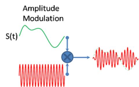
How Does Amplitude Modulation Work Quora
What Is Amplitude Modulation Types Advantages Disadvantages
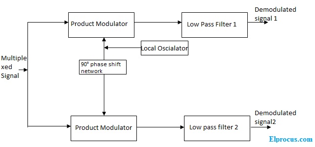
Quadrature Amplitude Modulation Block Diagram Its Working Principle

Circuit Diagram For Pulse Position Modulation In 2022 Circuit Design Circuit Diagram Circuit
Pulse Amplitude Modulation Pam Working Types Its Applications

Block Diagram Of Pulse Position Modulation Ppm Circuit Design Positivity Circuit
1

Pulse Amplitude Modulation Pam Working Types Its Applications
Pulse Amplitude Modulation Pam Working Types Its Applications
1
What Is Amplitude Modulation Types Advantages Disadvantages
1

Circadian Curve And Terminology A Model Curve Representing A Circadian Download Scientific Diagram

Circuit Diagram Of Pulse Position Modulation Ppm Modulator In 2022 Circuit Design Circuit Diagram Positivity
Why Do We Need Modulation Quora